This is Peddie Robotics, Team 5895's robot Gullinkambi for the 2022 FIRST Robotics Competition season:
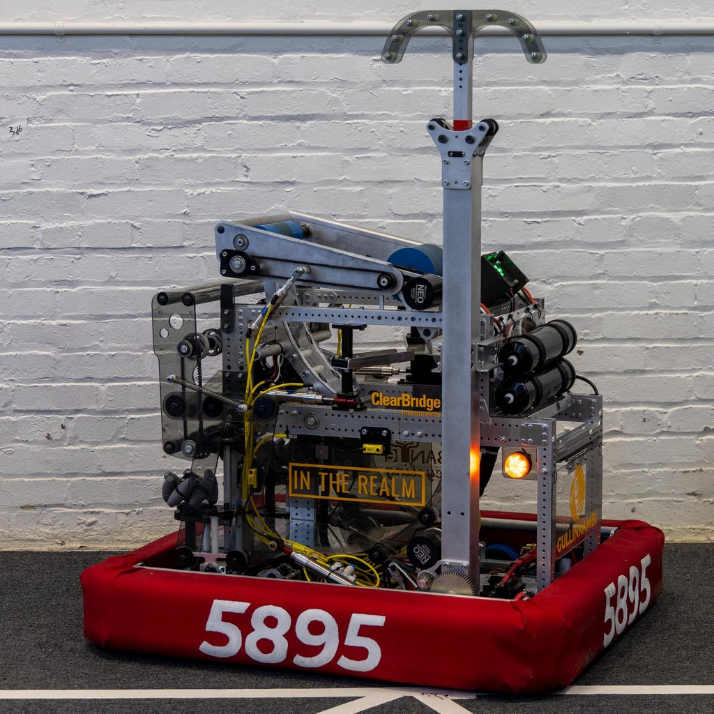
A masterpiece of engineering, our robot has multiple subsystems, including a flywheel shooter and shoots game pieces to earn points. This page will explain the physics of the flywheel shooter.
1) How is the ball shot?
The ball is shot by a flywheel rotating at a high angular speed, usually around 2000-3000 RPM for our robot, which translates to 2000*2*pi/60 = 209.44 rad/s and 3000*2*pi/60 = 314.16 rad/s. When the ball first touches the flywheel, it would be slipping, but when it exits the flywheel, the ball is not slipping against the wheel and the surface velocity of the wheel will equal to the surface velocity of the ball. The equation v =ωr can help us relate angular velocity and linear velocity. Our robot uses a 4 inch diameter Fairlane urethane flywheel so its radius would be 2 inches = 0.0508m. Thus, taking the lower end of 2000 RPM for the flywheel, its tangential velocity v_wheel = 209.44*0.0508 = 10.640 m/s. Our robot actually has a smaller 2 inch diameter wheel on the opposite side of the 4 inch wheel to reduce some backspin so that the ball would not bounce out of the goal. However, this interaction is very difficult to model and well beyond the scope of this post, so we will assume the second flywheel exerts no torque on the ball, and its exit velocity is just 10.640 m/s
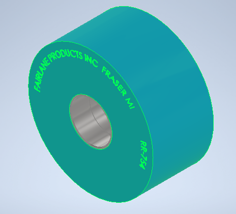
4 inch Fairlane urethane flywheel
2) How the ball moves in the air
After the ball exits the flywheel with the velocity v_ball, it enters projectile motion at an angle. Our robot has a double-angled hood so it can shoot at 82 degrees or 71 degrees depending on our robot's distance from the goal. We normally shoot at two positions: from the fender (against the wall of the goal at the blue 'X') and on the tarmac line (the red 'X'). I will be focusing on the 'tarmac' shot using the 71 degree angle. The ball is shot from our robot at around 26.5 inches above the ground into the high goal. The high goal is shaped like a upside down truncated cone, with a diameter of 53.5 inches. Its edge is 104 inches above the ground and 84 inches away from the fender.
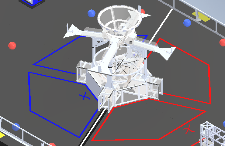
The field
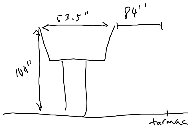
Simple diagram of the goal
Let's see if our shooter can successfully make it into the goal:
When an object is in projectile motion, the only force acting on it is the force of gravity. To analyze projectile motion, we should break it into its horizontal and vertical components. Using kinematic equations for the x and y components, we get:
When an object is in projectile motion, the only force acting on it is the force of gravity. To analyze projectile motion, we should break it into its horizontal and vertical components. Using kinematic equations for the x and y components, we get:
\[ \Delta x = x_0 + v_ox t + \frac{1}{2} at^2\], \[ \Delta y = y_0 + v_oy t + \frac{1}{2} at^2\]
We can set the initial x as zero and eliminate the last term since there is no acceleration in the x direction. Acceleration in the y direction is due to gravity, so we can plug in -g for a. Furthermore, the initial velocities in the x and y directions correspond to the components of the ball's launch velocity at an angle of 71 degrees. Thus we get:
\[ \Delta x = v_{ball} \cos\theta t \], \[ \Delta y = y_0 + v_{ball} \sin\theta t - \frac{1}{2} gt^2\]
These two equations can help us model the position of the ball at any time. Let's plug in the numbers we have (when converted from inches to meters), when the ball is 104 inches above the ground,
2.6416 = 0.6731 + 10.640*sin(71) - 9.8/2 * t^2
t = 1.28506472833
x = 10.640*cos(71) * 1.28506472833 = 4.45152225685
While this is more than the 3.5 meter (84"+53.5") area for the shot to be made in the goal, we simplified a lot of things so the calculated result is expected to be inaccurate. However, it works in real life:
t = 1.28506472833
x = 10.640*cos(71) * 1.28506472833 = 4.45152225685
While this is more than the 3.5 meter (84"+53.5") area for the shot to be made in the goal, we simplified a lot of things so the calculated result is expected to be inaccurate. However, it works in real life:
3) Shooting successive shots
As you might notice, our shooter shoots two balls at a time. To do this, we have to take into account the rotational kinetic energy lost by the flywheel after it shoots the first ball:
\[ K_{ball} + K_{rot_{ball}} = K_{rot_{wheel}} \]
Using energy equations, we know:
\[ K_{ball} = \frac{1}{2} m_{ball} v_{ball}^2 \]
\[ K_{rot_{ball}} = \frac{1}{2} I_{ball} \omega_{ball}^2 \]
\[ K_{rot_{wheel}} = \frac{1}{2} I_{wheel} \omega_{wheel}^2 \]
The mass of the ball is 9.5 oz. (0.2693kg) with radius 4.75" (0.12065m), while the mass of the flywheel is around 0.327kg. Assuming the coefficient of rotational inertia for the ball is 2/3 since it is just a sphere pumped with air and the coefficient of rotational inertia for the wheel is like a ring with radii 2 and 0.6875 inches (0.0508 and 0.0174625 meters):
\[ I_{ball} = \frac{2}{3} m_{ball} r_{ball}^2 = 0.00261336305 kg*m^2 \]
\[ I_{wheel} = \frac{m_{wheel}}{2} (R^2+r^2) = 0.00047184986 kg * m^2 \]
we know: \[v_{ball} = v_{wheel} \]
thus: \[ \omega_{ball} * r_{ball} = \omega_{wheel} * r_{wheel} \]
and \[ \omega_{wheel} = 209.44 rad/s \]
so \[ \omega_{ball} * 0.12065 = 209.44*0.0508 \]
so \[ \omega_{ball} = 88.185 rad/s \]
Plugging in the tangential velocity of the ball and angular velocities, we know:
\[ K_{rot_{ball}} = 10.1603797465 J \]
\[ K_{ball} = 15.24367264 J \]
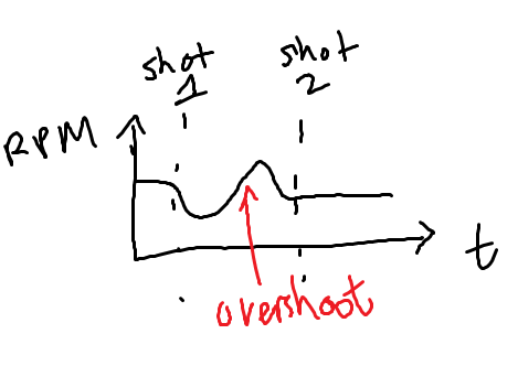
A total of 25.40 J of rotational kinetic energy would be lost in the flywheel, and thus its angular velocity and RPM would decrease. To counter this when shooting two consecutive balls, the robot automatically increases the RPM of the shooter once it senses that its RPM has dropped. Often times however, this causes the RPM to overshoot, but the robot quickly corrects this error. However, we need to time the second ball to shoot after this overshot so the RPM for the second shot is correct, and thus the exit velocity of the ball is correct.
thus: \[ \omega_{ball} * r_{ball} = \omega_{wheel} * r_{wheel} \]
and \[ \omega_{wheel} = 209.44 rad/s \]
so \[ \omega_{ball} * 0.12065 = 209.44*0.0508 \]
so \[ \omega_{ball} = 88.185 rad/s \]
Plugging in the tangential velocity of the ball and angular velocities, we know:
\[ K_{rot_{ball}} = 10.1603797465 J \]
\[ K_{ball} = 15.24367264 J \]
A total of 25.40 J of rotational kinetic energy would be lost in the flywheel, and thus its angular velocity and RPM would decrease. To counter this when shooting two consecutive balls, the robot automatically increases the RPM of the shooter once it senses that its RPM has dropped. Often times however, this causes the RPM to overshoot, but the robot quickly corrects this error. However, we need to time the second ball to shoot after this overshot so the RPM for the second shot is correct, and thus the exit velocity of the ball is correct.
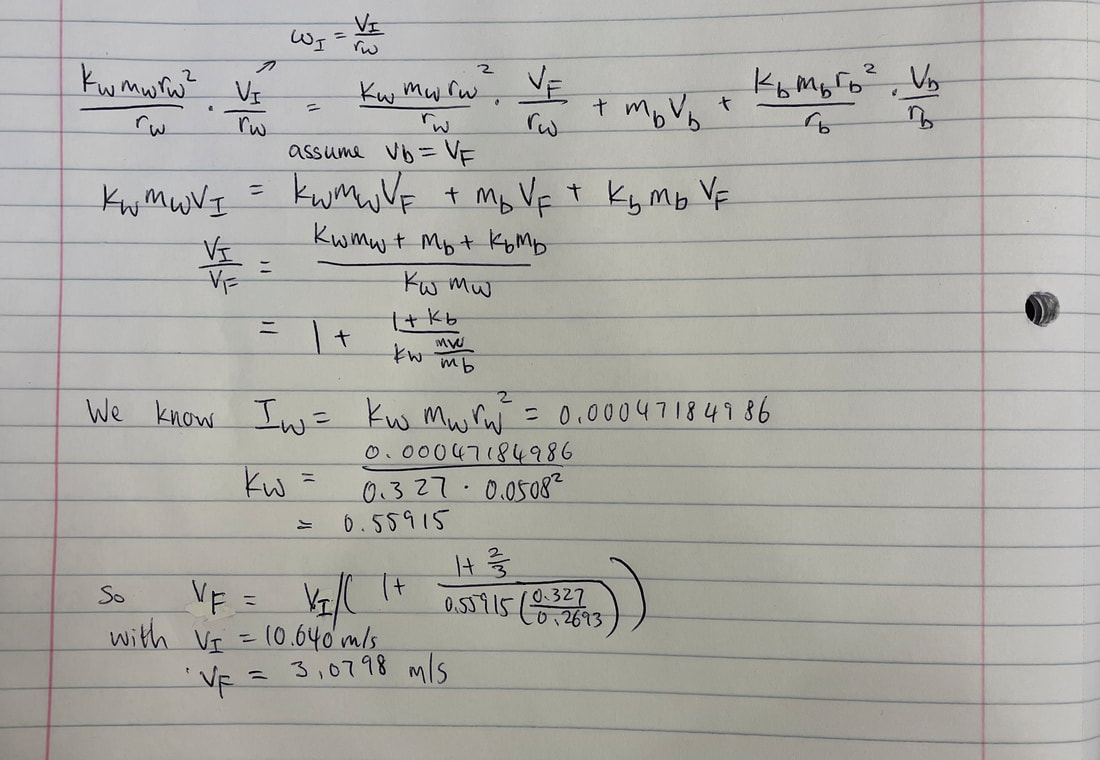
Another way to model this is through an inelastic collision where the momentum is conserved.
\[ \frac{I_{wheel} \omega_{initial}}{r_{wheel}} = \frac{I_{wheel} \omega_{final}}{r_{wheel}} + m_{ball} v_{ball} + \frac{I_{ball} \omega_{ball}}{r_{ball}} \]
we expand it to
\[ \frac{k_{wheel} m_{wheel} r_{wheel}^2}{r_{wheel}} * \frac{v_{initial}}{r_{wheel}} = \frac{I_{wheel} \omega_{final}}{r_{wheel}} + m_{ball} v_{ball} + \frac{I_{ball} \omega_{ball}}{r_{ball}}\]